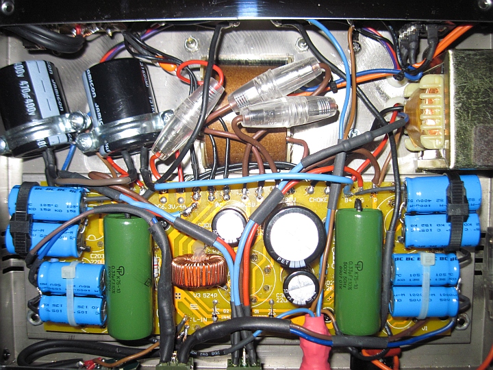
The audio signal path in a single-ended amplifier
Any single ended valve amplifier, like this, is highly sensitive to the quality of the power supply and of the employed capacitors. In fact the signal current, like any other, has to flow in a loop and, normally, whichever signal current flows across the cathode and the plate of the tube and the output transformer must complete a loop through the power rail decoupling capacitors and the cathode bypass capacitor (red output loop).
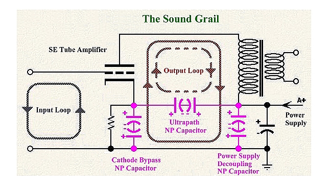
In particular, in The Sound Grail amplifier, an Ultrapath™ topology is employed. An additional capacitor connected as a bridge between the cathode of the tube and the A+ positive power rail keeps a portion of the signal current in a separate loop (red dasched output loop) which is shorter and away from both the power supply impedance and the cathode bypass capacitor. The main goal of this configuration is hum noise cancellation. This ultrapath capacitor is usually sized "mu-1" times smaller than the bypass capacitor (for KT77 the amplification factor mu is 11.5, thus the ultrapath capacitor is about one-tenth of the cathode one): the capacitive reactance of these two capacitors forms a 1:10 AC voltage divider, so a part of the power supply variations are injected at the cathode, which helps to reduce the power supply noise.
Where the signal current passes through a capacitor, the quality of this capacitor becomes very important: as far as why certain capacitors sound different than others, that becomes a hard question to answer and measure.
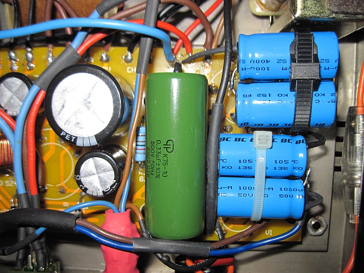
Back-to-back capacitors in cathode bypass and in ultrapath
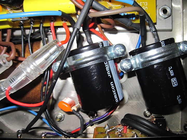
Two electrolytics connected back-to-back in power supply
This is the second time I'm using in a homemade amplifier non-polar electrolytic capacitors across DC power supply with excellent sonic results: the first time some years ago in a solid state headphone amplifier, and now in this my tube amplifier.
I do not claim I understand the scientific basis of it, but non-polar electrolytic capacitors offer subtle performance enhancements in power supply and bypass applications.
Unfortunately the measurements I did with non-professional equipments of the total harmonic distortion (THD% at 60Hz -30dB) and of the intermodulation distortion (IMD% at 60Hz & 7KHz in a 4:1 amplitude ratio), do not reveal any visible difference between polar and non-polar connection.
But after many blind test the improvement is so obvious to me that it cannot be only a placebo effect, as you probably are thinking about. When I say "excellent sonic results" is nothing related to a better frequency response or 3D improved soundstage or reduced distortion or lower noise or a better realism: "excellent sonic result" means to me "much less fatiguing listening" as it tends to produce somewhat clearer and smoother, with benefits for ambience as well.
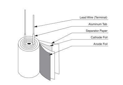
Non-polarized electrolytic capacitors have the same basic construction as polarized, except they use two anode foils with the electrolyte saturated separator interposed between, rather than an anode and a cathode. Two normal electrolytic (polarized) capacitors in series back-to-back (negative-to-negative joint) can work as a substitute.
How is made a polar capacitor
Back-to-back capacitor model
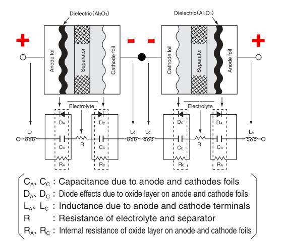
Two identical electrolytic back to back capacitors in series halve the total capacitance, but won't give double the voltage. With voltage across the pair, one will act as a cap while the other as a short. Thus a 470µF/400V plus 470µF/400V back to back series returns a 235µF/400V Non Polar capacitor.
It would be best to add diodes across at least the capacitor connected to ground in order to prevent reverse powering as electrolytic capapacitors can withstand some reverse voltage, but not too much. If we apply reverse voltage, the insulating oxide layer unforms and current flows, the capacitor heats up and generates gas.
Now the only reason for which current can flow in either direction is that the separator is wet, and that wetness dissociates into gas. It's the gas pressure that blows the capacitor. Large ones often have a pressure vent - if they don't, they can explode with some violence. But adding those "safety" diodes make the circuit too much non-linear, and in fact sound gets as it was before substituting the back-to-back capacitors. Thus, after some listening tests, I left the diodes out and, anyway, for the time being everything is working very quiet without them.
In fact what is important is not so much the duration for which the cap sees reverse voltage across it, but rather the total number of electrons that leak through the cap in the reverse direction: as long as you keep an electrolytic capacitor reverse-biased without drawing much current, all is fine. However, when you have two back-to-back, the forward-biased capacitor prevents a prolonged DC current from flowing. The 160mA fast fuse in the circuit is mandatory, as the forward-biased cap could fail short or increase too much the leakage current in the near future. Usually, as they are new, IL< 0.02CV, so in our case the leakage current is about 3mA, which looks safe to me.
During 2002 and 2003 Electronics World published a slew of articles by Cyril Bateman on capacitor distortion, dielectric absorption and several other subjects. Cyryl Bateman's studies about commercial Bi-polar electrolytic capacitors in audio circuits have proved that any significant DC bias voltage does unbalance a Bi-polar capacitor, resulting in increased second harmonic distortion, free from visible intermodulation and shows no measurable increase in third harmonic: everything is still little more than half a polar capacitor’s distortion measured even when using its optimum DC bias. Unfortunately the same studies proved that back-to-back pair distortion under significant DC bias is double that found with the commercial Bi-polar, thus the back-to-back distortion is similar to a polar capacitor’s one: this is exactly the same result I got from my above measurements with non-professional equipments.
Special Bi-polar aluminum electrolytic capacitors designed for bipolar DC operation are already available on the market today, and usually referred to as "non-polarized" or "bipolar" types. But the commercial maximum rated voltage available for electrolytic Bi-polar in DC applications is usually only 100VDC and they are very expensive, so the easiest solution here remains the back-to-back pair.
However two questions still remain open for me: first, why back-to-back electrolytic capacitors tend to produce a less fatiguing listening; second of course, an important parameter of electrolytics in particular, is how long they last under significant DC voltage bias. I can only say that after a couple of hundred hours of listening, they still run quiet and cool.